 - Collegamento all'originale")
Lost Techniques: Bond-out CPUs and In Circuit Emulation

These days, we take it for granted that you can connect a cheap piece of hardware to a microcontroller and have an amazing debugging experience. Stop the program. Examine memory and registers. You can see and usually change anything. There are only a handful of ways this is done on modern CPUs, and they all vary only by detail. But this wasn’t always the case. Getting that kind of view to an actual running system was an expensive proposition.
Today, you typically have some serial interface, often JTAG, and enough hardware in the IC to communicate with a host computer to reveal and change internal state, set breakpoints, and the rest. But that wasn’t always easy. In the bad old days, transistors were large and die were small. You couldn’t afford to add little debugging pins to each processor you produced.
This led to some very interesting workarounds. Of course, you could always run simulators on a larger computer. But that might not work in real time, and almost certainly didn’t have all the external things you wanted to connect to, unless you also simulated them.
The alternative? Create a special chip, often called a bond-out chip. These were usually expensive and had some way to communicate with the outside world. This might be a couple of pins, or there might be a bundle of wires coming out of the top of the chip. You replaced your microprocessor with the expensive bond-out chip and connected it to your very expensive in-circuit emulator.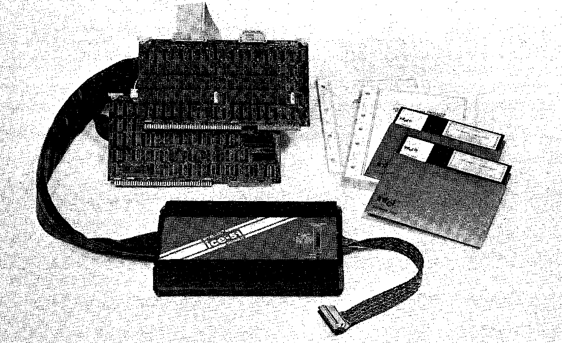
For example, the venerable 8051 had an 8051E chip that brought out the address and data bus lines for debugging. In fact, the history of the 8051 notes that they developed the bond-out chip first. The chip was bigger and sold in lower volumes, so it was more expensive. It needed not just connections but breakpoint hardware to stop the CPU at exactly the right time for debugging.
In some cases, the emulator probe was a board that sat between a stock CPU and the CPU socket. Of course, that meant you had to have room to accommodate the large board. Of course, it also assumes that at least your development board had a socket, although in those days it was rare to have an expensive CPU soldered right down to the board.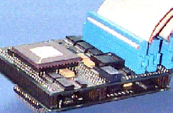
For example, the Lauterbach ICE-68300 here could take a bond-out chip or a regular chip, although it would be missing features if you didn’t have the special chip.
Of course, you can still find them in circuit emulators, but the difference is that they almost certainly have supporting hardware on the standard chip and simply use a serial communication protocol to talk to the on-chip hardware.
Of course, if you want an emulator for an old CPU, you have enough horsepower now that you can probably emulate it like with a modern processor, like the IZE80 does in the video below. Then you can incorporate all kinds of magical debugging features. But be careful what you take on. To properly mimic the hardware means tight timing for things like DRAM refresh and a complete understanding of all the bus timings involved.
But it can be done. In any event, on chip debugging or real in-circuit emulation, it sure makes life easier.
youtube.com/embed/Gdode3PfTbs?…