 - Collegamento all'originale")
Sfiduciati
I social sono un pericolo per la democrazia. Sono numerosi i saggi che argomentano questo aspetto distruttivo della comunicazione paritaria online che si afferma nelle logiche algoritmiche di Facebook, Tik Tok, Truth, eccetera. I social media sono spesso fonte e canale di propaganda e disinformazione.
Purtroppo la maggior parte delle persone non sa distinguere tra notizie vere e notizie false e le notizie false sono più virali di quelle vere. E questo è il danno principale che fanno alla democrazia.
Giovanni Boccia Artieri lo sintetizza bene nel suo ultimo libro, “Sfiduciati. Democrazia e disordine comunicativo nella società aperta” appena pubblicato da Feltrinelli, provando a dare qualche rimedio.
“I social media favoriscono ciò che funziona: e ciò che funziona polarizza, semplifica, infiamma. La democrazia ha bisogno di ascolto, mediazione, argomentazione. E se il conflitto algoritmico si consuma in millisecondi, il dissenso democratico richiede tempo”, ma è necessario.
La riflessione del professore di sociologia, prorettore dell’Università degli Studi di Urbino, già autore di diversi saggi sul tema è ovviamente molto più ampia.
Nel libro sostiene infatti che l’agorà pubblica negli ultimi anni è stata inquinata soprattutto da tre fenomeni. Il primo è l’ingresso nell’era della post-verità. In questa fase della comunicazione infatti non è tanto importante la verità e neanche la validità la coerenza e l’utilità con cui si comunicano concetti semplici e complessi ma il modo in cui le persone vi reagiscono. Chi sa gestire quelle reazioni può farci credere a ciò che vero non è. Il secondo fenomeno è la piattaformizzazione di Internet. Secondo questa famosa teorizzazione di Van Dijck e Poell, le piattaforme che connettono gli individui tra di loro permettendogli di fruire e consumare servizi non offerti dagli Stati, creano strutture sociali disomogenee producendo valori
con un potenziale rischio etico. Il terzo fenomeno è la fringe democracy, cioè l’annullamento del confine tra cio che è legittimo e cio che non lo è, insieme al livellamento delle opinioni sempre più autoreferenziali.
Queste tre dinamiche creano la società esposta, un ambiente in cui la comunicazione e la sfera pubblica, attraversate dalla sfiducia, sono diventate vulnerabili.


Looking at a Real Fake Raspberry Pi RP2040 Board

Since the RP2040 microcontroller is available as a stand-alone component, it’s easy enough for third parties to churn out their own variations — or outright clones of — the Raspberry Pi Pico. Thus we end up with for example AliExpress sellers offering their own versions that can be significantly cheaper than the genuine article. The ones that [electronupdate] obtained for a test and decapping session cost just $2.25 a pop.

As can be seen in the top image, the board from AliExpress misses the Raspberry Pi logo on the silkscreen for obvious reasons, but otherwise appears to feature an identical component layout. The QSPI Flash IC is marked on the die as BY250156FS, identifying it as a Boya part.
Niggles about flash ROM quality aside, what’s perhaps most interesting about this teardown is what eagle-eyed commentators spotted on the die shot of the RP2040. Although on the MCU the laser markings identify the RP2040 as a B2 stepping, the die clearly identifies it as an ‘RP2 B0’ part, meaning B0 stepping. This can be problematic when you try to use the USB functionality due to hardware USB bugs in the B0 and B1 steppings.
As they say, caveat emptor.
youtube.com/embed/uQ3kNFOhTIw?…
Windows? Linux? Browser? Same Executable

We’ve been aware of projects like Cosmopolitan that allow you to crank out a single executable that will run on different operating systems. [Kamila] noticed that the idea was sound, but that the executables were large and there were some limitations. So she produced a 13K file that will run under Windows, Linux, or even in a Web browser. The program itself is a simple snake game.
There seems to be little sharing between the three versions. Instead, each version is compressed and stitched together so that each platform sees what it wants to see. To accommodate Windows, the file has to start with a PE header. However, there is enough flexibility in the header that part of the stub forms a valid shell script that skips over the Windows code when running under Linux.
So, essentially, Windows skips the “garbage” in the header, which is the part that makes Linux skip the “garbage” in the front of the file.
That leaves the browser. Browsers will throw away everything before an <HTML> tag, so that’s the easy part.
Should you do this? Probably not. But if you needed to make this happen, this is a clear template for how to do it. If you want to go back to [Kamila’s] inspiration, we’ve covered Cosmopolitan and its APE format before.
Philips Kid’s Kit Revisited

[Anthony Francis-Jones], like us, has a soft spot for the educational electronic kits from days gone by. In a recent video you can see below, he shows the insides of a Philips EE08 two-transistor radio kit. This is the same kit he built a few months ago (see the second video, below).
Electronics sure look different these days. No surface mount here or even printed circuit boards. The kit had paper cards to guide the construction since the kit could be made into different circuits.
The first few minutes of the video recap how AM modulation works. If you skip to about the ten-minute mark, you can see the classic instruction books for the EE08 and EE20 kits (download a copy in your favorite language), which were very educational.
There were several radios in the manual, but the one [Anthony] covers is the two-transistor version with a PNP transistor as a reflex receiver with a diode detector with a second transistor as an audio power amplifier.
We covered [Anthony’s] original build a few months ago, but we liked the deep dive into how it works. We miss kits like these. And P-Boxes, too.
youtube.com/embed/eC2wwNq92mw?…
youtube.com/embed/PWPHGEWwKbU?…
Making Code a Hundred Times Slower With False Sharing
")
Writing good, performant code depends strongly on an understanding of the underlying hardware. This is especially the case in scenarios like those involving embarrassingly parallel processing, which at first glance ought to be a cakewalk. With multiple threads doing their own thing without having to nag the other threads about anything it seems highly doubtful that even a novice could screw this up. Yet as [Keifer] details in a recent video on so-called false sharing, this is actually very easy, for a variety of reasons.

With a multi-core and/or multi-processor system each core has its own local cache that contains a reflection of the current values in system RAM. If any core modifies its cached data, this automatically invalidates the other cache lines, resulting a cache miss for those cores and forcing a refresh from system RAM. This is the case even if the accessed data isn’t one that another core was going to use, with an obvious impact on performance.
The worst case scenario as detailed and demonstrated using the Google Benchmark sample projects, involves a shared global data structure, with a recorded hundred times reduction in performance. Also noticeable is the impact on scaling performance, with the cache misses becoming more severe with more threads running.
A less obvious cause of performance loss here is due to memory alignment and how data fits in the cache lines. Making sure that your data is aligned in e.g. data structures can prevent more unwanted cache invalidation events. With most applications being multi-threaded these days, it’s a good thing to not only know how to diagnose false sharing issues, but also how to prevent them.
youtube.com/embed/WIZf-Doc8Bk?…
Dad Makes Kid’s Balance Bike Into Electric Snow Trike Like a Boss

The balance bikes toddlers are rocking these days look like great fun, but not so great in the snow. Rather than see his kid’s favourite toy relegated to shed until spring, [John Boss] added electric power, and an extra wheel to make one fun-looking snow trike. Like a boss, you might say.
Physically, the trike is a delta configuration: two rear wheels and one front, though as you can see the front wheel has been turned into a ski. That’s not the most stable configuration, but by shifting the foot pegs to the front wheel and keeping the electronics down low, [John] is able to maintain a safe center of gravity. He’s also limiting the throttle so kiddo can’t go dangerously fast– indeed, the throttle control is in the rear electronics component. The kid just has a big green “go” button.
Bit-banging the throttle, combined with the weight of the kiddo up front, creates a strong tendency towards wheel-spin, but [John] fixes that with a some cleverly printed TPU paddles zip-tied to the harbor-freight wheels and tires he’s hacked into use. Those wheels are fixed to a solid axle that’s mounted to flat plate [John] had made up to attach to the bike frame. It’s all surprisingly solid, given that [John] is able to demonstrate the safety factor by going for a spin of his own. We would have done the same.
We particularly like the use of a tool battery for hot-swappable power. This isn’t the first time we’ve seen a kid’s toy get the tool battery treatment, but you aren’t limited to mobile uses. We’ve seen the ubiquitous 18V power packs in everything from fume extractors to a portable powerpack that can even charge a Tesla.
youtube.com/embed/L_3cA8oZP8w?…
A New Life For An Old Amplifier

An audio amplifier was once a fairly simple analogue device, but in recent decades a typical home entertainment amplifier will have expanded to include many digital functions. When these break they are often proprietary and not easy to repair, as was the case with a broken Pioneer surround-sound device given to [Boz]. It sat on the shelf for a few years until he had the idea of a jukebox for his ripped CDs, and his returning it to life with a new main board is something to behold.
Internally it’s a surprisingly modular design, meaning that the front panel with its VFD display and driver were intact and working, as were the class AB amplifier and its power supply. He had the service manual so reverse engineering was straightforward, thus out came the main board in favor of a replacement. He took the original connectors and a few other components, then designed a PCB to take them and a Raspberry Pi Pico and DAC. With appropriate MMBASIC firmware it looks as though it was originally made this way, a sense heightened by a look at the motherboard inside (ignoring a couple of bodges).
We like seeing projects like this one which revive broken devices, and this one is particularly special quality wise. We’re more used to seeing it with gaming hardware though.
FLOSS Weekly Episode 860: Elixir Origin Story

This week Jonathan and Randal chat with Jose Valim about Elixir! What led Jose to create this unique programming language? What do we mean that it’s a functional language with immutability?
youtube.com/embed/H4lC4JNUxOs?…
Did you know you can watch the live recording of the show right on our YouTube Channel? Have someone you’d like us to interview? Let us know, or have the guest contact us! Take a look at the schedule here.
play.libsyn.com/embed/episode/…
Direct Download in DRM-free MP3.
If you’d rather read along, here’s the transcript for this week’s episode.
Places to follow the FLOSS Weekly Podcast:
Theme music: “Newer Wave” Kevin MacLeod (incompetech.com)
Licensed under Creative Commons: By Attribution 4.0 License
hackaday.com/2026/01/14/floss-…
Genetic Therapy Aims To Bring Hearing To Those Born Deaf

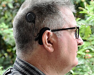
For those born with certain types of congenital deafness, the cochlear implant has been a positive and enabling technology. It uses electronics to step in as a replacement for the biological ear that doesn’t quite function properly, and provides a useful, if imperfect, sense of hearing to its users.
New research has promised another potential solution for some sufferers of congenital deafness. Instead of a supportive device, a gene therapy is used to enable the biological ear to function more as it should. The result is that patients get their sense of hearing, not from a prosthetic, but from their own ears themselves.
New Therapy
There are a number of causes of congenital deafness, each of which presents in its own way. In the case of OTOF-related hearing loss, it comes down to a genetic change in a single critical protein. The otoferlin gene is responsible for making the protein of the same name, and this protein is critical for normal, functional hearing in humans. It’s responsible for enabling the communication of signals between the inner hair cells in the ear, and the auditory nerve which conducts these signals to the brain. However, in patients with a condition called autosomal recessive deafness 9, a non-functional variant of the otoferlin gene prevents the normal production of this protein. Without the proper protein available, the auditory nerve fails to receive the proper signals from the hair cells in the ear, and the result is profound deafness.
The typical treatment for this type of congenital hearing loss is the use of a cochlear implant. This is an electronic device that uses a microphone to pick up sound, and then translates it into electrical signals which are sent to electrodes embedded in the cochlear. These simulate the signals that would normally come from the ear itself, and provide a very useful sense of hearing to the user. However, quality and fidelity is strictly limited compared to a fully-functional human ear, and they do come with other drawbacks as is common with many prosthetic devices.
The better understanding that we now have of OTOF-related hearing loss presented an opportunity. If it were possible to get the right protein where it needed to be, it might be possible to enable hearing in what are otherwise properly-formed ears.
The treatment to do that job is called DB-OTO. It’s a virus-based gene therapy which is able to deliver a working version of the OTOF gene. It uses a non-pathogenic virus to carry the proper genetic code that produces the otoferlin protein. However, it’s no good if this gene is expressed in just any context. Thus, it’s paired with a special DNA sequence called a Myo15 promoter which ensures the gene is only expressed in cochlear hair cells that would normally express the otoferlin protein. Treatment involves delivering the viral gene therapy to one or both ears through a surgical procedure using a similar approach to implanting cochlear devices.
An early trial provided DB-OTO treatment to twelve patients, ranging in age from ten months to sixteen years. eleven out of twelve patients developed improved hearing within weeks of treatment with DB-OTO. Nine patients were able to achieve improvements to the point of no longer requiring cochlear implants and having viable natural hearing.
Six trial participants could perceive soft speech, and three could hear whispers, indicating a normal level of hearing sensitivity. Notably, hearing improvements were persistent and there were some signs of speech development in three patients in the study. The company behind the work, Regeneron, is also eager to take the learnings from its development and potentially apply it to other kinds of hearing loss from genetic causes.
DB-OTO remains an experimental treatment for now, but regulatory approvals are being pursued for its further use. It could yet prove to be a viable and effective treatment for a wide range of patients affected by this genetic issue. It’s just one of a number of emerging treatments that use viruses to deliver helpful genetic material when a patient’s own genes don’t quite function as desired.
DK 10x17 - AGCOM vs CloudFlare
Una legge, specie una discutibile come il Piracy Shield, si può discutere e modificare, ma intanto la si rispetta. E il CEO di CloudFlare può attaccarsi.
spreaker.com/episode/dk-10x17-…
ESP32-P4 Powers Retro Handheld after a Transplant

The ESP32-P4 is the new hotness on the microcontroller market. With RISC-V architecture and two cores running 400 MHz, to ears of a certain vintage it sounds more like the heart of a Unix workstation than a traditional MCU. Time’s a funny thing like that. [DynaMight] was looking for an excuse to play with this powerful new system on a chip, so put together what he calls the GB300-P4: a commercial handheld game console with an Expressif brain transplant.
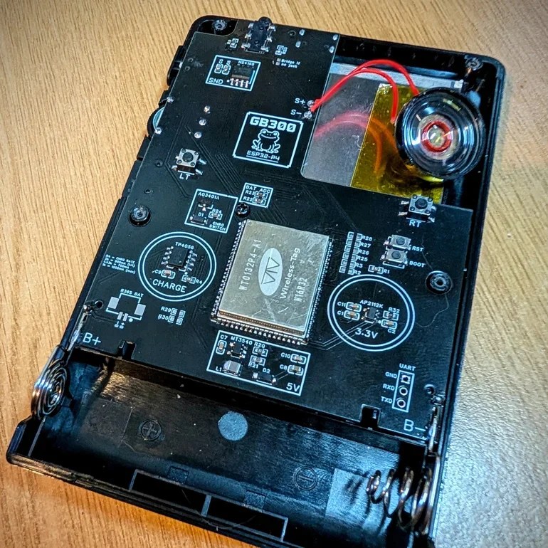
If the build quality on this handheld looks suspiciously professional, that’s because it is: [DynaMight] started with a GB300, a commercial emulator platform. Since the ESP32-P4 is replacing a MIPS chip clocked at 914 MHz in the original — which sounds even more like the heart of a Unix workstation, come to think of it — the machine probably doesn’t have better performance than it did from factory unless its code was terribly un-optimized. In this case, performance was not the point. The point was to have a handheld running RetroGo on this specific chip, which the project has evidently accomplished with flying colours. If you’ve got a GB300 you’d rather put an “Expressif Inside” sticker on, the project is on github. Otherwise you can check out the demo video below. (DOOM starts at 1:29, because of course it runs DOOM.)
The last P4 project we featured was a Quadra emulator; we expect to see a lot of projects with this chip in the new year, and they’re not all going to be retrocomputer-related, we’re sure. If you’re cooking up something using the new ESP32, or know someone who is, you know what to do.
youtube.com/embed/FW7MTuJyUNA?…
Clone Wars: IBM Edition

If you search the Internet for “Clone Wars,” you’ll get a lot of Star Wars-related pages. But the original Clone Wars took place a long time ago in a galaxy much nearer to ours, and it has a lot to do with the computer you are probably using right now to read this. (Well, unless it is a Mac, something ARM-based, or an old retro-rig. I did say probably!)
IBM is a name that, for many years, was synonymous with computers, especially big mainframe computers. However, it didn’t start out that way. IBM originally made mechanical calculators and tabulating machines. That changed in 1952 with the IBM 701, IBM’s first computer that you’d recognize as a computer.
If you weren’t there, it is hard to understand how IBM dominated the computer market in the 1960s and 1970s. Sure, there were others like Univac, Honeywell, and Burroughs. But especially in the United States, IBM was the biggest fish in the pond. At one point, the computer market’s estimated worth was a bit more than $11 billion, and IBM’s five biggest competitors accounted for about $2 billion, with almost all of the rest going to IBM.
So it was somewhat surprising that IBM didn’t roll out the personal computer first, or at least very early. Even companies that made “small” computers for the day, like Digital Equipment Corporation or Data General, weren’t really expecting the truly personal computer. That push came from companies no one had heard of at the time, like MITS, SWTP, IMSAI, and Commodore.
The IBM PC
The story — and this is another story — goes that IBM spun up a team to make the IBM PC, expecting it to sell very little and use up some old keyboards previously earmarked for a failed word processor project. Instead, when the IBM PC showed up in 1981, it was a surprise hit. By 1983, there was the “XT” which was a PC with some extras, including a hard drive. In 1984, the “AT” showed up with a (gasp!) 16-bit 80286.
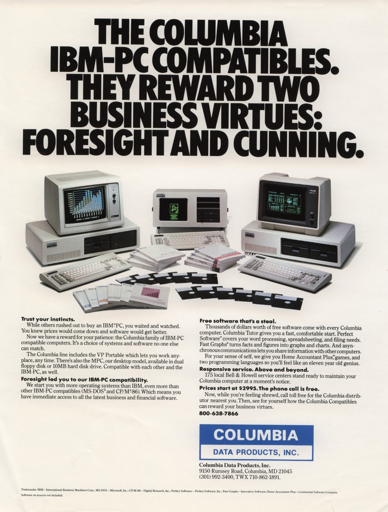
The personal computer market had been healthy but small. Now the PC was selling huge volumes, perhaps thanks to commercials like the one below, and decimating other companies in the market. Naturally, others wanted a piece of the pie.
youtube.com/embed/VslekgnIXDo?…
Send in the Clones
Anyone could make a PC-like computer, because IBM had used off-the-shelf parts for nearly everything. There were two things that really set the PC/XT/AT family apart. First, there was a bus for plugging in cards with video outputs, serial ports, memory, and other peripherals. You could start a fine business just making add-on cards, and IBM gave you all the details. This wasn’t unlike the S-100 bus created by the Altair, but the volume of PC-class machines far outstripped the S-100 market very quickly.
In reality, there were really two buses. The PC/XT had an 8-bit bus, later named the ISA bus. The AT added an extra connector for the extra bits. You could plug an 8-bit card into part of a 16-bit slot. You probably couldn’t plug a 16-bit card into an 8-bit slot, though, unless it was made to work that way.
The other thing you needed to create a working PC was the BIOS — a ROM chip that handled starting the system with all the I/O devices set up and loading an operating system: MS-DOS, CP/M-86, or, later, OS/2.
Protection
IBM didn’t think the PC would amount to much so they didn’t do anything to hide or protect the bus, in contrast to Apple, which had patents on key parts of its computer. They did, however, have a copyright on the BIOS. In theory, creating a clone IBM PC would require the design of an Intel-CPU motherboard with memory and I/O devices at the right addresses, a compatible bus, and a compatible BIOS chip.
But IBM gave the world enough documentation to write software for the machine and to make plug-in cards. So, figuring out the other side of it wasn’t particularly difficult. Probably the first clone maker was Columbia Data Products in 1982, although they were perceived to have compatibility and quality issues. (They are still around as a software company.)
Eagle Computer was another early player that originally made CP/M computers. Their computers were not exact clones, but they were the first to use a true 16-bit CPU and the first to have hard drives. There were some compatibility issues with Eagle versus a “true” PC. You can hear their unusual story in the video below.
youtube.com/embed/0wdunM5XZwo?…
One of the first companies to find real success cloning the PC was Compaq Computers, formed by some former Texas Instruments employees who were, at first, going to open Mexican restaurants, but decided computers would be better. Unlike some future clone makers, Compaq was dedicated to building better computers, not cheaper.
Compaq’s first entry into the market was a “luggable” (think of a laptop with a real CRT in a suitcase that only ran when plugged into the wall; see the video below). They reportedly spent $1,000,000 to duplicate the IBM BIOS without peeking inside (which would have caused legal problems). However, it is possible that some clone makers simply copied the IBM BIOS directly or indirectly. This was particularly easy because IBM included the BIOS source code in an appendix of the PC’s technical reference manual.
Between 1982 and 1983, Compaq, Columbia Data Products, Eagle Computers, Leading Edge, and Kaypro all threw their hats into the ring. Part of what made this sustainable over the long term was Phoenix Technologies.
youtube.com/embed/fwvLu9aSkmQ?…
Rise of the Phoenix
Phoenix was a software producer that realized the value of having a non-IBM BIOS. They put together a team to study the BIOS using only public documentation. They produced a specification and handed it to another programmer. That programmer then produced a “clean room” piece of code that did the same things as the BIOS.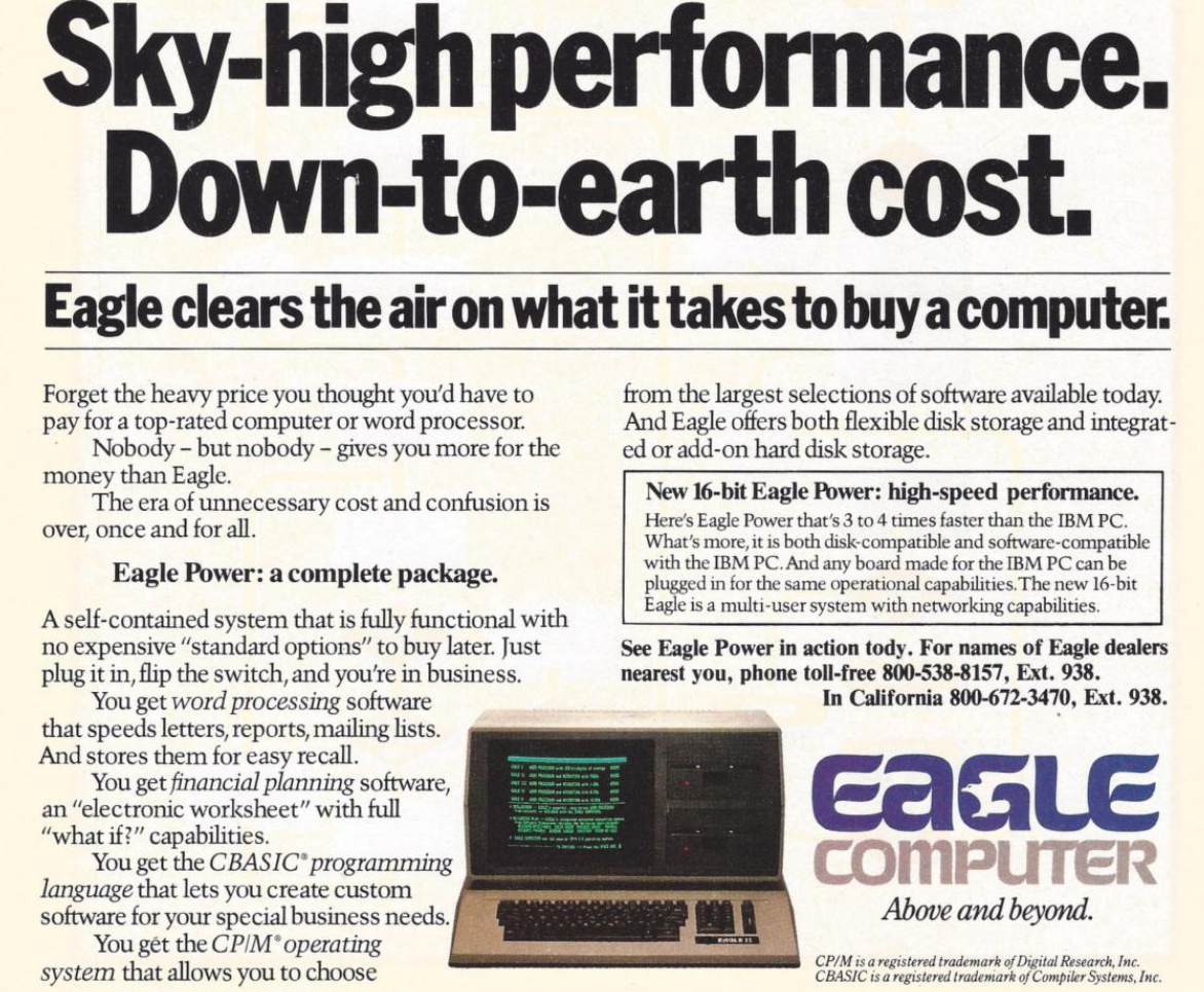
This was important because, inevitably, IBM sued Phoenix but lost, as they were able to provide credible documentation that they didn’t copy IBM’s code. They were ready to license their BIOS in 1984, and companies like Hewlett-Packard, Tandy, and AT&T were happy to pay the $290,000 license fee. That fee also included insurance from The Hartford to indemnify against any copyright-infringement lawsuits.
Clones were attractive because they were often far cheaper than a “real” PC. They would also often feature innovations. For example, almost all clones had a “turbo” mode to increase the clock speed a little. Many had ports or other features as standard that a PC had to pay extra for (and consume card slots). Compaq, Columbia, and Kaypro made luggable PCs. In addition, supply didn’t always match demand. Dealers often could sell more PCs than they could get in stock, and the clones offered them a way to close more business.
Issues
Not all clone makers got everything right. It wasn’t odd for a strange machine to have different interrupt handling than an IBM machine or different timers. Another favorite place to err involved AT/PC compatibility.
In a base-model IBM PC, the address bus only went from A0 to A19. So if you hit address (hex) FFFFF+1, it would wrap around to 00000. Memory being at a premium, apparently, some programs depended on that behavior.
With the AT, there were more address lines. Rather than breaking backward compatibility, those machines have an “A20 gate.” By default, the A20 line is disabled; you must enable it to use it. However, there were several variations in how that worked.
Intel, for example, had the InBoard/386 that let you plug a 386 into a PC or AT to upgrade it. However, the InBoard A20 gating differed from that of a real AT. Most people never noticed. Software that used the BIOS still worked because the InBoard’s BIOS knew the correct procedure. Most software didn’t care either way. But there was always that one program that would need a fix.
The original PC used some extra logic in the keyboard controller to handle the gate. When CPUs started using cache, the A20 gating was moved into the CPU for many generations. However, around 2013, most CPUs finally gave up on gating A20.
The point is that there were many subtle features on a real IBM computer, and the clone makers didn’t always get it right. If you read ads from those days, they often tout how compatible they are.
Total War!
IBM started a series of legal battles against… well… everybody. Compaq, Corona Data Systems, Handwell, Phoenix, AMD, and anyone who managed to put anything on the market that competed with “big blue” (one of IBM’s nicknames).
IBM didn’t win anything significant, although most companies settled out of court. Then they just used the Phoenix BIOS, which was provably “clean.” So IBM decided to take a different approach.
In 1987, IBM decided they should have paid more attention to the PC design, so they redid it as the PS/2. IBM spent a lot of money telling people how much better the PS/2 was. They had really thought about it this time. So scrap those awful PCs and buy a PS/2 instead.
Of course, the PS/2 wasn’t compatible with anything. It was made to run OS/2. It used the MCA bus, which was incompatible with the ISA bus, and didn’t have many cards available. All of it, of course, was expensive. This time, clone makers had to pay a license fee to IBM to use the new bus, so no more cheap cards, either.
You probably don’t need a business degree to predict how that turned out. The market yawned and continued buying PC “clones” which were now the only game in town if you wanted a PC/XT/AT-style machine, especially since Compaq beat IBM to market with an 80386 PC by about a year.
Not all software was compatible with all clones. But most software would run on anything and, as clones got more prevalent, software got smarter about what to expect. At about the same time, people were thinking more about buying applications and less about the computer they ran on, a trend that had started even earlier, but was continuing to grow. Ordinary people didn’t care what was in the computer as long as it ran their spreadsheet, or accounting program, or whatever it was they were using.
Dozens of companies made something that resembled a PC, including big names like Olivetti, Zenith, Hewlett-Packard, Texas Instruments, Digital Equipment Corporation, and Tandy. Then there were the companies you might remember for other reasons, like Sanyo or TeleVideo. There were also many that simply came and went with little name recognition. Michael Dell started PC Limited in 1984 in his college dorm room, and by 1985, he was selling an $800 turbo PC. A few years later, the name changed to Dell, and now it is a giant in the industry.
Looking Back
It is interesting to play “what if” with this time in history. If IBM had not opened their architecture, they might have made more money. Or, they might have sold 1,000 PCs and lost interest. Then we’d all be using something different. Microsoft retaining the right to sell MS-DOS to other people was also a key enabler.
IBM stayed in the laptop business (ThinkPad) until they sold to Lenovo in 2005. They would also sell them their server business in 2014.
Things have changed, of course. There hasn’t been an ISA card slot on a motherboard in ages. Boot processes are more complex, and there are many BIOS options. Don’t even get us started on EMS and XMS. But at the core, your PC-compatible computer still wakes up and follows the same steps as an old school PC to get started. Like the Ship of Theseus, is it still an “IBM-compatible PC?” If it matters, we think the answer is yes.
If you want to relive those days, we recently saw some new machines sporting 8088s and 80386s. Or, there’s always emulation.
The People vs Digital Omnibus
THIS IS DIGITAL POLITICS. But it's not Monday. I'm Mark Scott, and I apologize for the one-day delay in this week's newsletter. I've come down with what I really hope isn't Covid-19, so please forgive any typos in the dispatch below. Normal Monday transmission resumes next week.

— New polling suggests European citizens may not be as keen about the bloc's digital revamp as policymakers and industry.
— The United States' departure from more than 60 international organizations is another death knell in the open, interoperable internet.
– Despite global efforts, the US still dominates the market for data centers.
Let's get started:
The ARCTURUS Computer Developed at Sydney University in the 1960s

[State of Electronics] have released their latest video about ARCTURUS, the 14th video in their series The Computer History of Australia.
ARCTURUS was a research computer system developed on a shoestring budget at Sydney University in the 1960s, and was in service until 1975. Particularly the system was developed by [David Wong] as a part of his PhD thesis: The design and construction of the digital computers snocom, nimbus and arcturus (PDF). [David] worked in collaboration with [Kevin R. Rosolen] who is interviewed in the video.
The machine is described as a fixed-point, binary, parallel, single address, general-purpose digital computer using packaged diode-transistor circuits. Ferrite-core memory was used instead of drum memory because drum memory was too slow and performance was a high priority feature. For the same reason parallel features were implemented where serial might have been done more simply, if it hadn’t been so slow. In addition to the ferrite-core there were paper-tape peripherals and control panels.
The machine supported 32 distinct instructions and had a 13-bit address space allowing it to directly address 8,192 words, each word comprising 20-bits. Those word bits were one sign bit and nineteen magnitude bits for fixed-point two’s complement binary numbers.
We covered The Computer History of Australia by [State of Electronics] back when they released their 5th video in the series, Australia’s Silliac Computer, if you’re interested in more history of computing in Australia.
youtube.com/embed/h7cw7BNOZ-Y?…
Electronic Nose Sniffs out Mold

It turns out, that mold is everywhere. The problem is when it becomes too much, as mold infestations can have serious health effects on both humans and animals. Remediation is extremely expensive, too. So there are plenty of benefits to finding mold early. Now, German researchers are proposing an electronic “nose” that uses UV-activated tin oxide nanowires that change resistance in the presence of certain chemicals, and they say it can detect two common indoor mold species.
The nanowire sensors can detect Staachybotrys chartarum and Chaetominum globosum. The real work, though, is in the math used to determine positive versus negative results.
Traditional methods take some sort of physical sample that is sent to a lab and require days to process. However, trained dogs can also smell mold, but as you might expect, there aren’t many dogs trained to find mold. Besides, the training is expensive, you have to maintain the dog all the time, and if the dog knows what kind of mold it is, it can’t say. So an electronic nose that can give fast, specific results is quite attractive.
Even if you don’t care about mold, the data crunching to classify the sensor data has application to many types of sensors. They used training to build multiple models, then they combine the outputs using a regression algorithm to predict the true output. Finally, they use a majority voting technique to combine the results of the model and the regression output.
Could you make a sensor like this? Reading section 4.2 of the paper, it looks like you need a pretty stout set of lab gear to play. But the math ideas are certainly something you could replicate or use as a starting point for your own sensor fusion projects.
Want a deep dive into sensor fusion? You should have been at the Hackaday Superconference a few years ago. Luckily, you can still watch [Christal’s] talk about fusing multiple streams of sensor data.
Optimizing a Desktop, 3D Printed Wind Tunnel
 vs a compact version (below)")
You’ve heard of wind tunnels– get some airflow going over a thingy, put some some smoke on, and voila! Flow visualization. How hard could it be? Well, as always, the devil is in the details and [toast] is down in there with him with this Hot-Wheels sized wind tunnel video.
To get good, laminar flow inside of a wind tunnel, there are important ratios to be followed– the inlet and outlet diameters must relate to the interior size to get the correct slope on the contraction and exhaust cones. You need a flow straightener on both ends. All of it can be easily 3D printed, as [toast] shows, but you have to know those design rules and pay attention to, which [toast] does… this time. One of his “don’t do this” examples in this video is previous build of his where he did not follow all the rules, and the difference is clear.
Now, unless you’re hooked on flow visualizations —guilty— or are a Hot-Wheels aficionado, since that’s what this wind tunnel is sized for, you probably won’t rush to gumroad to buy [toast]’s STLs. On the other hand, if you pay attention to the lessons [toast] has learned in this video you can apply them to wind tunnels of whatever size and construction technique you need, be it cardboard or junk box plastic and get a more stable result.
youtube.com/embed/D60PdZJggyk?…
The Distroless Linux Future May Be Coming

Over the decades the number of Linux distributions has effectively exploded, from a handful in the late ’90s to quite literally hundreds today, not counting minor variations. There lately seems to be a counter-movement brewing in response to this fragmentation, with Project Bluefin’s Distroless project being the latest addition here. Also notable are KDE’s efforts, with KDE Linux as its own top-down KDE-based distro, but now with a switch to BuildStream from Arch likely as a distroless move.
It should be clear that there is no obvious course here yet, and that opinions are very much divided. The idea of ‘Linux’ becoming a more singular OS appeals to some, while to others it’s the antithesis of what ‘Linux’ is about. This much becomes clear in [Brodie Robertson]’s exploration of this topic as well.
The way to think about ‘distroless’ is that there is a common base using the Freedesktop SDK on which the customization layer is applied, such as Bluefin, KDE or Gnome’s environments. You could think of this base as the common runtime, using the Freedesktop standards for interoperability for a user-selected layer that’s installed on top. This way the idea of basing a distro on a specific distro is tossed out in favor of something that’s vaguely reminiscent of the Linux Standard Base attempt at standardization.
It’ll be fascinating to see how things will move from here, as there are definite arguments to be made in favor of less fragmentation and resultingly less duplicated effort. In many ways this would bring Linux closer to for example FreeBSD, which avoids the Linux Chaos Vortex problem by having a singular codebase. FreeBSD ‘distros’ like GhostBSD and NomadBSD are therefore essentially just specialized customizations that target a sub-group of FreeBSD users.
Of course, when we start talking about package managers and other base-distro specific features, we may very well risk igniting the same problems that tore apart the LSB so many years ago. Will we also standardize on RPM over DEB package files and kin, or something else?
youtube.com/embed/k6qCtIHFu_c?…
Michelson Interferometer Comes Home Cheap

We suspect there are three kinds of people in the world. People who have access to a Michelson Interferometer and are glad, those who don’t have one and don’t know what one is, and a very small number of people who want one but don’t have one. But since [Longest Path Search] built one using 3D printing, maybe the third group will dwindle down to nothing.
If you are in the second camp, a Michelson interferometer is a device for measuring very small changes in the length of optical paths (oversimplifying, a distance). It does this by splitting a laser into two parts. One part reflects off a mirror at a fixed distance from the splitter. The other reflects off another, often movable, mirror. The beam splitter also recombines the two beams when they reflect back, producing an interference pattern that varies with differences in the path length between the splitter and the mirror. For example, if the air between the splitter and one mirror changes temperature, the change in the refraction index will cause a minute difference in the beam, which will show up using this instrument.
The device has been used to detect gravitational waves, study the sun and the upper atmosphere, and also helped disprove the theory that light is transmitted through a medium known as luminiferous aether.
The tolerances for such a device are tight, but within the capability of modern 3D printers. The CAD files are online. The key was the mirror mounts, which use springs and thumbscrews. So you do need some hardware and, oh yeah, a laser, although that’s not as hard to obtain as it once was. You obviously can’t 3D print the mirrors or the beam splitter either.
The post claims the device is cheap because the bill of materials was roughly $3, although that didn’t include the beamsplitter, which would bring the cost up to maybe $20. The device, in theory, could detect distance changes as small as one wavelength of the laser, which is around 650nm. Not bad for a few bucks.
Not all Michelsons use lasers. The man behind the Michelson instrument also worked out how to do Fourier analysis with a mechanical computer.
Keebin’ with Kristina: the One with the Cheap-O Keyboard

All right, I’ll cut to the chase: Cheap03xD is mainly so cheap because the PCB falls within a 10 x 10 cm footprint. The point was to make a very affordable keyboard — all the parts come to ~40 Euro (~$47). So it would seem that [Lander03xD_] succeeded.

Those are MMD Princess silent switches, which I wouldn’t choose, but [Lander03xD_] is taking this board to the office, so I get it. They sure are a nice shade of pink, anyway, and they go really well with the pastels of the DSA keycaps and the bezel.
One cool thing to note is that the PCBs are reversible, like the ErgoDox. This isn’t [Lander03xD_]’s first board, and it won’t be the last.
Now, let’s talk batteries. [Saixos] pointed out that the design doesn’t appear to include a protection circuit. In case you can’t tell from where you’re sitting, those are nice!nano clones that [Lander03xD_] is using, and they expect a protection circuit.
[Lander03xD_] is going to look through the docs and see what’s what. The goal is not to have any daughter boards, so this may take some rethinking.
Via reddit
Arc Raiders Keyboard Looks the Part
So Arc Raiders is this cool-looking, stripe-logoed, multiplayer extraction shooter that just came out a couple of months ago for all the platforms. It’s not something I could personally play as it’s way too immersive (read: time-consuming), but it definitely looks good, much like this keyboard that [RunRunAndyRun] designed to play it.

No matter; just make a new one. Why not? This rustic beauty runs on the Waveshare RP2040 Zero. The case was 3D printed on a Prusa Mk4, which you’d never know unless you blew up the picture. And then [RunRunAndyRun] gave it that nice patina using Panduro hobby acrylics and a bit of weathering powder.
For now, it’s working pretty well, though [RunRunAndyRun] is still perfecting the keymap. If you’d like to build one yourself, the STLs are available here, and the firmware is on GitHub.
Thanks for the tip, [John]!
The Centerfold: Witch’s Brew

Do you rock a sweet set of peripherals on a screamin’ desk pad? Send me a picture along with your handle and all the gory details, and you could be featured here!
Historical Clackers: the Keystone

This spartan beauty was named after the state in which it was made, Pennsylvania. Manufactured between 1898 and 1903, the Keystone was invented by William Prehn Quentell.
Quentell was living in Kansas City, MO when he first applied for a patent, and later moved to the east coast. At the time, the machine was nameless. The patent looks nothing like the finished product pictured here, but the genesis of the key feature of this “poor man’s Hammond” is there — the swinging type sector.
What this means is that the Keystone has its type on a half wagon wheel, which is evident in the patent drawing. The glyphs are molded around the outside edge of the wheel, which gets rotated into the correct position with each keystroke. This type wheel could be easily changed out for different fonts.
To imprint the paper, a spring-driven hammer strikes from behind, pushing the paper and ribbon against the type wheel. The paper is loaded into a cylindrical holder in the rear, and unfurls as one types.
So, why was it a poor man’s Hammond? Well, for one, the patent image looks like a Hammond. But the poor part is felt the hardest in the makeup of the typewriter.
In the early Keystone examples, the carriage rails were made of pig iron. Why? It’s a simple case of lateral integration. The factory that was retrofitted to manufacture the machine had previously been the Lochiel iron mill, a producer of pig iron. They were just using up old stock, I imagine.
The Keystone featured two Shift keys on the left, one for Caps and one for Figures. It was a comparatively inexpensive at $40, and then later, $35 (around $1,200 today).
Production was supposed to begin in May of 1898. But by June of ’99, “the company has been unable to fill the orders which are piling up at the works.” Sounds like your average Kickstarter. Quentell was already working on his next project by 1902, the Postal typewriter.
Finally, a Keyboard That Charges Your Phone
So this article mainly centers on the new little Blackberry-esque number from Clicks which might just be my next phone, except that it doesn’t actually telephone. Clicks is meant to be your second phone, the one you use for emailing and such. You can pre-order it for $399 if you put a $199 deposit down before February 27th. If you decide to drop the full four hundo as an early bird, you’ll get two additional back covers, which slightly change the look of the phone.
But I’d like to talk about the add-on Power Keyboard for smart phones that Clicks is also dropping at CES this year. Do you miss your Sidekick? Well, here’s a sliding keyboard with multiple positions for differently-sized smart phones, tablets, and even smart TVs. (Because forget typing with the remote control.)
It uses a 2,150 mAh battery and attaches via MagSafe or Qi2, but it also can be used with the case on. When paired with a smart TV, you just use it by itself. Honestly, it looks kind of hard to type on without the phone for support. But I don’t use the smart features of my TV, so whatever.
Honestly, I will probably start by getting the keyboard, which is $79 for early birds through their site, and $109 later on. Pre-orders started a week ago, so I guess I should get on that.
Got a hot tip that has like, anything to do with keyboards? Help me out by sending in a link or two. Don’t want all the Hackaday scribes to see it? Feel free to email me directly.
Chasing The Coca-Cola Recipe

One of the most widely recognised product brands in the world is probably Coca-Cola, and its formula is famously kept a secret through precautions that probably rival those of many nation states. There are other colas, and there are many amateurs who have tried to copy Coke’s flavour, but in well over a century, nobody has managed it. Why does [LabCoatz] think his attempt will be successful where others failed? He has friends with their own mass spectrometers.
‘The video below the break is a nearly half-hour exploration into food chemistry and the flavour profile of the well-known soft drink. It’s easy to name many of the ingredients, but some, such as acetic acid, are unexpected. Replicating the contribution from Coke’s de-cocainised coca leaf extract requires the purchase of some of the constituent chemicals in pure form. Its value lies in showing us how flavour profiles are built up, and the analytical methods used in their decoding.
He makes the point that Coke has never patented the formula because to do so would reveal it, but perhaps in that lies the real point. The value in a secret formula for brands such as Coke lies not in the secret itself, as it’s not difficult to make a refreshing cola drink. Instead, it’s the mystique of their product having a secret recipe that matters. Since this isn’t the recipe itself but something that’s supposed to taste a lot like it, that mystique stays intact. He’s not positioning his Lab-Cola as the real thing, so while we might have used a different label colour and font just to make sure, we’re guessing he’s safe from the lawyers. If you’re interested in the legal grey areas surrounding perceived infringement, though, it’s a topic we’ve looked at before.
youtube.com/embed/TDkH3EbWTYc?…
Thanks [Hans] for the tip!
La civiltà dei dati. Rivista
Civiltà dei dati è una bella rivista. Prosecuzione ideale della Civiltà delle macchine che dal 1953 al 1979 ha contribuito a modellare la cultura dell’innovazione nel nostro paese, aspira oggi come allora a intrecciare il dialogo tra scienza, tecnologica e sperimentazione letteraria e artistica con un focus specifico sull’ontologia del dato. Proprio quel dato che consente scelte e previsioni, il dato che ci anticipa e rappresenta nel mondo digitale e che è il carburante delle nuove macchine IA è il centro e al centro della rivista. Diretta da Jaime D’Alessandro, storica penna tecnologica dell’Espresso e di Repubblica, è un contenitore di alcune delle migliori firme del pensiero contemporaneo in lingua italiana, Floridi, Taddeo, Benanti, Aresu, e del giornalismo tech come Iacona, Aluffi, Sterling e altri. I primi quattro numeri della rivista, frutto di un progetto della Fondazione Leonardo, direttrice generale la giornalista Helga Cossu, sono stati dedicati a quattro grandi temi d’attualità: lo spazio, la mente, gli archivi, l’IA e i digital twins.
La rivista è molto curata, sia dal punto di vista grafico, con una chiara impronta visiva, sia per i contenuti.
Il primo numero è una parata delle stelle femminili protagoniste della ricerca spaziale; il secondo, è incentrato sugli effetti psicologici della tecnologia e dei social network; il terzo si fonda sul rapporto tra analogico e digitale per parlare di archivi. Particolarmente interessanti sono le riflessioni di Paolo Benanti in questo numero tre quando parla dell’importanza della memoria selettiva, cioè di quel processo che è umano ma non macchinico, di ritenere solo quello che serve, come accadeva con le biblioteche. Benanti fa anche un riferimento importante all’etica dell’IA quando ricorda che gli strumenti, tutti gli strumenti, non sono neutri, ma forme d’ordine e disposizioni di potere. Nella rivista numero 4 va letta l’intervista a Lucilla Sioli, direttrice dell’ufficio europeo per l’IA. Detto per inciso è quella graficamente più bella (recupera le copertine di Urania). Ma è sempre nel numero 3 che troviamo la chicca: una storia a fumetti dell’impareggiabile Milo Manara basato sulla storia della biblioteca meccanica di Jorge Luis Borges. Chissà se quell’utopia bella e terribile della macchina da scrivere universale, oggi rappresentata dall’IA generativa, potrà mai predirci il futuro dentro a un libro. Accetteremmo anche qualche errore di sintassi.
«Civiltà dei dati. 2025. Fondazione Leonardo. Direttore Jaime D’Alessandro». Nella foto i primi quattro numeri.

The Intel 8087 and Conditional Microcode Tests

Continuing his reverse-engineering of the Intel 8087, [Ken Shirriff] covers the conditional tests that are implemented in the microcode of this floating point processing unit (FPU). This microcode contains the details on how to perform the many types of specialized instructions, like cos and arctan, all of which decode into many microcode ops. These micro ops are executed by the microcode engine, which [Ken] will cover in more detail in an upcoming article, but which is effectively its own CPU.
Conditional instructions are implemented in hardware, integrating the states of various functional blocks across the die, ranging from the instruction decoder to a register. Here, the evaluation is performed as close as possible to the source of said parameter to save on wiring.
Implementing this circuitry are multiplexers, with an example shown in the top die shot image. Depending on the local conditions, any of four pass transistors is energized, passing through that input. Not shown in the die shot image are the inverters or buffers that are required with the use of pass transistors to amplify the signal, since pass transistors do not provide that feature.
Despite how firmly obsolete the 8087 is today, it still provides an amazing learning opportunity for anyone interested in ASIC design, which is why it’s so great that [Ken] and his fellow reverse-engineering enthusiasts keep plugging away at recovering all this knowledge.
The SCSI Film Scanner Resurrection

[Ronan] likes 35mm film photography, but the world, of course, has gone digital. He picked up an Epson FilmScan 200 for about €10. This wonder device from 1997 promised to convert 35mm film to digital at 1200 DPI resolution. But there was a catch: it connects via SCSI. Worse, the drivers were forever locked to Windows 95/98 and Mac System 7/8.
In a surprise twist, though, [Ronan] recently resurrected a Mac SE/30 with the requisite SCSI port and the System 7 OS. Problem solved? Not quite. The official software is a plugin for Photoshop. So the obvious answer is to write new software to interact with the device.
First, of course, you have to figure out how the device works. A service manual provided clues that, as far as the SCSI bus knew, the device wasn’t a scanner at all, but a processor. The processor, though, used SCSI as a simple pipe to handle Epson’s standard “ESC/I” protocol.
Armed with that information and a knowledge of the Mac’s SCSI Manager API, the rest is just coding. Well, that is until [Ronan] tried to scan the other five negatives in the six-negative film carrier. He was frustrated until he found an old patched SANE driver for the scanner from 2002. By looking at how it worked, he was able to figure out how to switch to the other negatives.
Color scanning also took a little coaxing. The scanner returns three monochrome images, one for each color channel. Some assembly, then, is required. In the end, though, the project was a complete success. Can’t find a FilmScan 200? Don’t have a SCSI port? There’s always the roll-your-own approach.
A Much Faster Mac On A Microcontroller

Emulating older computers on microcontrollers has been a staple of retrocomputing for many years now, with most 8-bit and some 16-bit machines available on Atmel, ARM, or ESP32 platforms. But there’s always been a horsepower limit, a point beyond which a microcontroller is no longer enough, and a “proper” computer is needed. One of those barriers now appears to have been broken, as microcontroller-based emulation moves into the 32-bit era. [Amcchord] has the Basilisk II emulator ported to the ESP32-P4 platform, providing a 68040 Mac able to run OS8.1. This early-1990s-spec machine might not seem like much in 2026, but it represents a major step forward.
The hardware it uses is the M5Stack Tab5, and it provides an emulated Mac with up to 16 MB of memory. Remember, in 1992 this would have been a high-spec machine. It manages a 15 frames per second refresh rate, which is adequate for productivity applications. The emulator uses the Tab5’s touchscreen to emulate the Mac mouse alongside support for USB input devices. To 1990 hackers, it’s almost the Mac tablet you didn’t know you would want in the future.
We like this project, both because it’s advancing the art of emulation on microcontrollers, and also because it delivers a computer that’s useful for some of the things you might have done with a Mac in 1992 and could even do today. Pulling this out on the train back then would have blown people’s minds. There’s even a chance that MacOS on something like this would turn a few heads in 2026. It’s certainly not the first emulated Mac we’ve seen though.
Reverse-Engineering the Tamagotchi IR Connection

The Tamagotchi Connection is a series of Tamagotchi toys that took the original portable pet concept and mixed things up with a wireless connection, which allowed you to interact with the pets of other proud Tamagotchi owners. This wireless connection is implemented using an infrared transceiver, somewhat like IrDA, but as [Zach Resmer] discovered while reverse-engineering this connection, it’s actually what is called ‘Nearly NEC’ by [Natalie Silvanovich], who has a GitHub repository full of related Tamagotchi hacking tools and ROM dumps.
With the protocol figured out, creating a transceiver for low-bitrate infrared communication isn’t particularly hard. In this case, it was implemented using an RP2040 MCU and an appropriate IR LED and receiver pair. This Tamagometer project was also implemented as an app for the Flipper Zero, and a custom PCB called the Pico TamaBadge by [Daniel Weidman].
There’s a web application associated with [Zach]’s project using a Web Serial-enabled browser (i.e. Chrome). The serial protocol is somewhat documented in the patent for the device’s connection feature, which makes it relatively easy to implement yourself.
ESP with EEG — No, Not That ESP!

While EEG research might help you figure out extrasensory perception, we won’t be betting on it. However, if you want to read EEG data and use an ESP32, [Cerelog-ESP-EEG] might be the right project for you. The commercial project is an 8-channel biosensing board suitable for EEG, EMG, ECG, and brain-computer interface studies. However, the company says, “We love the hacker community! We explicitly grant permission for Personal & Educational Use.” We love you too.
They do require you to agree not to sell boards you are building, and they give you schematics, but no PC board layout. That’s understandable, although we’d guess that achieving good results will require understanding how to lay out highly sensitive circuits.
What you do get is the schematic and the firmware source. They note that you may have to modify the firmware if you want to switch modes, change gain, or enable haptic feedback, among other things. At the application layer, the device is compatible with Lab Streaming Layer, and there is a fork of OpenBCI (brain control interface) that understands how to talk to the board.
Even if you don’t want to directly clone the device, there’s a ton of information here if you are interested in EEG or any other small signal acquisition. We’ve seen a number of interfaces like this, but we are still waiting to see a killer application.
A 1990s VNA Gets An LCD

A Vector Network Analyser, or VNA, is the ultimate multi-tool of RF test equipment. They can now be had in not very capable form for almost pocket money prices, but the professional-grade ones cost eye-watering sums. Enough to make an older VNA for a few hundred on eBay a steal, and [W3AXL] has just such a device in an HP 8714C. It’s the height of 1990s tech with a floppy drive and a green-screen CRT, but he’s homing right in on the VGA monitor port on the back. Time for a colour LCD upgrade!
There are two videos below the break, posted a year apart, because as we’re sure many of you will know, events have a habit of getting in the way of projects. In the first, we see the removal of the CRT module and safe extraction of its electronics, followed by the crafting of a display bezel for the LCD. Meanwhile, the second video deals with the VNA itself, extracting the VGA signal and routing it forward to the new module.
We’re struck not for the first time by the high quality of the construction in this piece of test equipment; it’s not only substantial but well designed for maintenance and disassembly. [W3AXL] sensibly leaves the RF part alone, but both CRT and mainboard modules slide out with minimal screw removals and few problems in reassembly.
He goes the extra mile with a second iteration of the display mount and a curved print to fit the CRT shape in the front panel. The result is a colour display on the instrument, and we’re guessing, a much lighter device, too.
If VNAs are new to you, then you might wish to learn a little about them,
youtube.com/embed/AuNkZtfcmqU?…
youtube.com/embed/vi5H66_kYRc?…
Simplifying the SmartKnob

A knob can make a surprisingly versatile interface, particularly if it’s the SmartKnob, which builds a knob around a BLDC motor for programmable haptic response. It can rotate freely or with a set resistance, spring back to a fixed point when released, stick at detent points, and completely change its behavior as the interface demands. For people inexperienced in electronic assembly, though, smartknobs can be difficult to assemble. That’s why [Kokensha Tech] designed a simpler version, while at the same time letting it use a wider range of BLDC motors.
In addition to a motor, the original design used a magnetic encoder to detect position and a strain gauge to detect pressure on the knob. A circular LCD on the knob itself provided visual feedback, but it also required the motor to have a hollow center shaft. The LCD control wires running through the shaft proved tricky to assemble. [Kokensha Tech] moved the display out of the knob and onto a separate breakout board, which plugs into the controller board. This greatly broadens the range of compatible motors, since they no longer need a hollow shaft.
The motor now fits on a separate carrier board, which makes it easier to swap out different motors. The carrier board has mounting holes sized for a wide variety of motors, and four different types of motor connectors. [Kokensha Tech] also redesigned the rest of the PCB for easier soldering, while avoiding components with narrow pin spacing whenever possible. The original design used a LILYGO T-micro32 Plus MCU. The ESP32 is both cheaper and easier to solder, so it was a no-brainer to swap it in.
We’ve covered the original SmartKnob before, including a more in-depth look at its design. We’ve also seen another project use BLDCs and field-oriented control to make haptic knobs.
youtube.com/embed/7kSSMUdl7_k?…
It’s Not a Leica, It’s a Lumix

There’s an old adage in photography that the best camera in the world is the one in your hand when the shot presents itself, but there’s no doubt that a better camera makes a difference to the quality of the final image. Among decent quality cameras the Leica rangefinder models have near cult-like status, but the problem is for would-be Leica owners that they carry eye-watering prices. [Cristian Băluță] approached this problem in s special way, by crafting a Leica-style body for a Panasonic Lumix camera. Given the technology relationship between the Japanese and German companies, we can see the appeal.
While the aesthetics of a Leica are an important consideration, the ergonomics such as the position of the lens on the body dictated the design choices. He was fortunate that the internal design of the Lumix gave plenty of scope for re-arrangement of parts, given that cameras are often extremely packed internally. Some rather bold surgery to the Lumix mainboard and a set of redesigned flex PCBs result in all the parts fitting in the CNC machined case, and the resulting camera certainly looks the part.
The write-up is in part a journey through discovering the process of getting parts manufactured, but it contains a lot of impressive work. Does the performance of the final result match up to its looks? We’ll leave you to be the judge of that. Meanwhile, take a look at another Leica clone.
The Time Clock Has Stood the Test of Time

No matter the item on my list of childhood occupational dreams, one constant ran throughout: I saw myself using an old-fashioned punch clock with the longish time cards and everything. I now realize that I have some trouble with the daily transitions of life. In my childish wisdom, I somehow knew that doing this one thing would be enough to signify the beginning and end of work for the day, effectively putting me in the mood, and then pulling me back out of it.
But that day never came. Well, it sort of did this year. I realized a slightly newer dream of working at a thrift store, and they use something that I feel like I see everywhere now that I’ve left the place — a system called UKG that uses mag-stripe cards to handle punches. No it was not the same as a real punch clock, not that I have experience with a one. And now I just want to use one even more, to track my Hackaday work and other projects. At the moment, I’m torn between wanting to make one that uses mag-stripe cards or something, and just buying an old punch clock from eBay.
I keep calling it a ‘punch clock’, but it has a proper name, and that is the Bundy clock. I soon began to wonder how these things could both keep exact time mechanically, but also create a literal inked stamp of said time and date. I pictured a giant date stamper, not giant in all proportions, but generally larger than your average handheld one because of all the mechanisms that surely must be inside the Bundy clock. So, how do these things work? Let’s find out.
Bundy’s Wonder
Since the dawn of train transportation and the resulting surge of organized work during the industrial revolution, employers have had a need to track employees’ time. But it wasn’t until the late 1880s that timekeeping would become so automatic.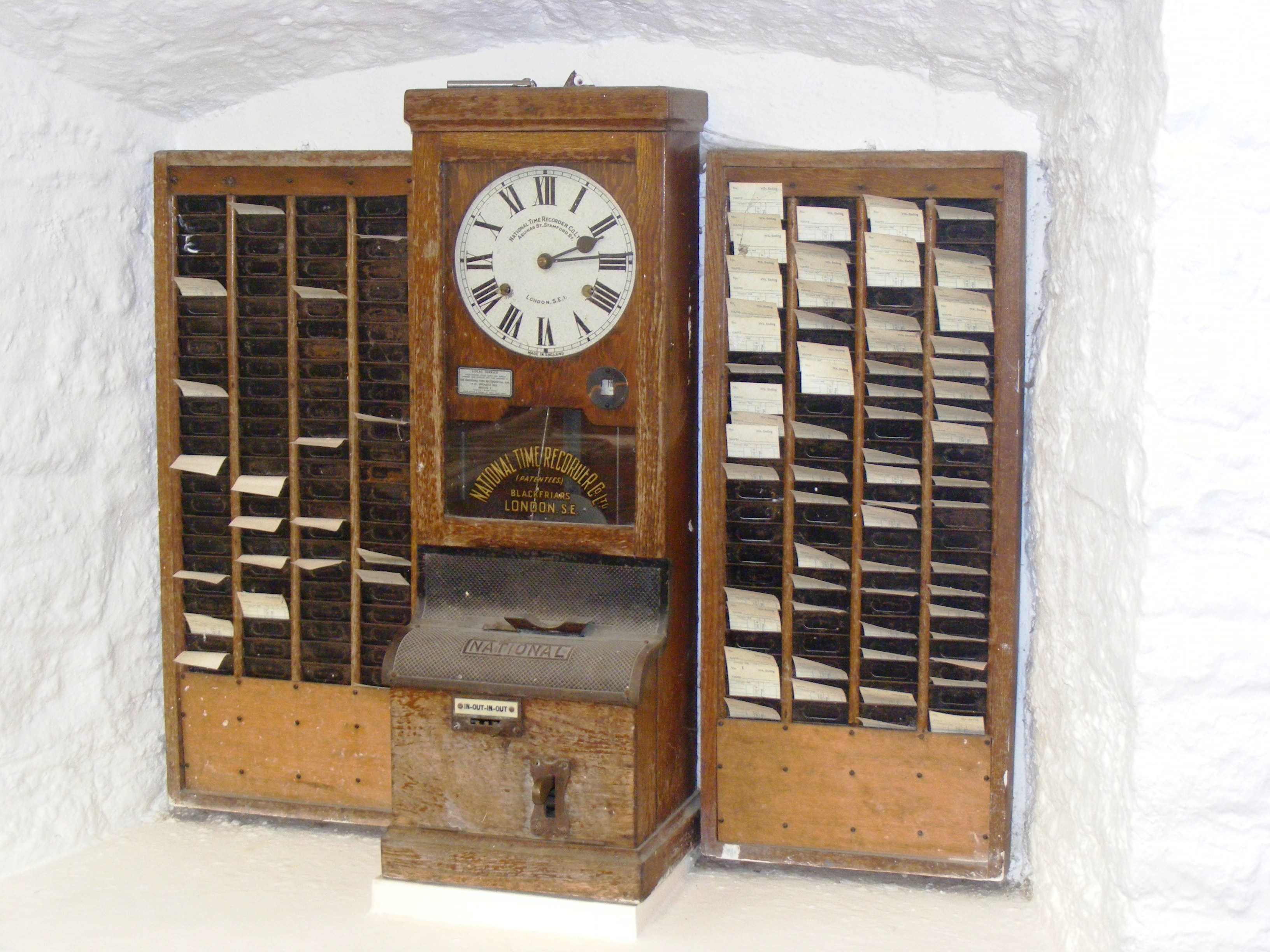
Willard Le Grand Bundy was a jeweler in Auburn, New York who invented a timekeeping clock in 1888. A few years later, Willard and his brother Harlow formed a company to mass-produce the clocks.
By the early 20th century, Bundy clocks were in use all over the world to monitor attendance. The Bundy Manufacturing Company grew and grew, and through a series of mergers, became part of what would become IBM. They sold the time-keeping business to Simplex in 1958.
Looking at Willard Le Grand Bundy’s original clock, which appears to be a few feet tall and demonstrates the inner workings quite beautifully through a series of glass panels, it’s no wonder that it is capable of time-stamping magic.
Part of that magic is evident in the video below. Workers file by the (more modern) time clock and operate as if on autopilot, grabbing their card from one set of pockets, inserting it willy-nilly into the machine, and then tucking it in safely on the other side until lunch. This is the part that fascinates me the most — the willy-nilly insertion part. How on Earth does the clock handle this? Let’s take a look.
youtube.com/embed/kCpWF5UXfQ4?…
Okay, first of all, you probably noticed that the video doesn’t mention Willard Le Grand Bundy at all, just some guy named Daniel M. Cooper. So what gives? Well, they both invented time-recording machines, and just a few years apart.
The main difference is that Bundy’s clock wasn’t designed around cards, but around keys. Employees carried around a metal key with a number stamped on it. When it was time clock in or out, they inserted the key, and the machine stamped the time and the key number on a paper roll. Cooper’s machine was designed around cards, which I’ll discuss next. Although the operation of Bundy’s machine fell out of fashion, the name had stuck, and Bundy clocks evolved slightly to use cards.
Plotting Time
You would maybe think of time cards as important to the scheme, but a bit of an afterthought compared with the clock itself. That’s not at all the case with Cooper’s “Bundy”. It was designed around the card, which is a fixed size and has rows and columns corresponding to days of the week, with room for four punches per day.
Essentially, the card is mechanically indexed inside the machine. When the card is inserted in the top slot, it gets pulled straight down by gravity, and goes until it hits a fixed metal stop that defines vertical zero. No matter how haphazardly you insert the card, the Bundy clock takes card of things. Inside the slot are narrow guides that align the card and eliminate drift. Now the card is essentially locked inside a coordinate system.
So, how does it find the correct row on the card? You might think that the card moves vertically, but it’s actually the punching mechanism itself that moves up and down on a rack-and-pinion system. This movement is driven by the timekeeping gears of the clock itself, which plot the times in the correct places as though the card were a piece of graph paper.
In essence, the time of day determined the punch location on the card, which wasn’t a punch in the hole punch sense, but a two-tone ink stamp from a type of bi-color ribbon you can still get online.
There’s a date wheel that selects the row for the given day, and a time cam to select the column. The early time clocks didn’t punch automatically — the worker had to pull a lever. When they did so, the mechanism would lock onto the current time, and the clock would fire a single punch at the card at the given coordinates.
Modern Time
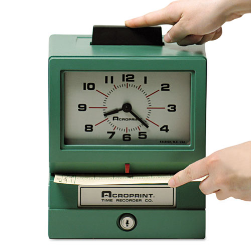
By the mid-century, time clocks had become somewhat simpler. No longer did the machine do the plotting for you. Now you put them in sideways, in the front, and use the indicator to get the punch in the right spot. It’s not hard to imagine why these gave way to more modern methods like fingerprint readers, or in my case, mag-stripe cards.
This is the type of time clock I intend to buy for myself, though I’m having trouble deciding between the manual model where you get to push a large button like this one, and the automatic version. I’d still like to build a time clock, too, for all the finesse and detail it could have by comparison. So honestly, I’ll probably end up doing both. Perhaps you’ll read about it on these pages one day.
Drive 1024×600 Pixels via I2C with an ATtiny85

If you need to drive a big screen for a project, it’s fair to say your first thought isn’t going to be to use the ATtiny85. With just 512 bytes of RAM and 8 kilobytes of flash memory, the 8-bit micro seems a little cramped to drive, say, a 10″ screen. Yet that’s exactly what [ToSStudio] is doing with TinyTFT_LT7683: 1024 x 600 pixels of TFT goodness, over I2C no less.
The name kind of gives away the secret: it won’t work on just any TFT display. It’s using properties of the LT7683 display driver, though if you don’t have one of those, the RA8875 is also compatible. Those drivers can take more than just a pixel stream– a good thing, since you’d be hard pressed to get that many pixels streaming from an ATtiny. These are character/graphic display drivers, which means you can get them to draw both characters and graphics on the screen if you speak the lingo.
It’s still not blazing fast; the documentation suggests “static or moderately dynamic UIs” as the suggested use case, and a clock is of the pre-programmed examples. From that, we can surmise that you can get 1 FPS or better with this code. You’re limited both by the simple micro-controller and the bandwidth of the I2C bus, but within those limits this seems like a very powerful technique.
This isn’t the first ATtiny graphics library to blow our minds, but if you really want an impressive graphics demo from the little micro that could, you really need to race the beam.
Thanks to [Thomas Scherer] for the tip!
The Issue With Wii U Gamepads and How to Clone Them
")
How hard would it be to clone the Wii U gamepad, the quirky controller with its unique embedded screen? This is the question that [MattKC] faced as he noticed the complete lack of Wii U gamepad replacements from either Nintendo or third-parties, leading him down the rabbit hole of answering said question.

Although unloved and even despised in compared to the Nintendo Wii, the Wii U was a solid system in its own right. One of its interesting additions was the gamepad controller, whose screen games used for features like a private screen during multiplayer and 3DS-like map screens. Its main weakness is however that the Wii U gamepad was considered an irreplaceable part of the console, which is obviously not fun if your gamepad breaks and your console along with it.
The Wii U console and gamepad communicate via 5 GHz 802.11n WiFi, but in order to deter other parties from simply hopping onto the access point, Nintendo slightly obfuscated this WiFi standard. Specifically the WPA authentication was modified by a byte swap in the PTK, rendering every existing WiFi stack incompatible with the Wii U.
")
Knowing this, the key is to use a platform that allows one to pre-break WPA in a similar fashion, such as is possible on e.g. Linux and BSD. Along with the use of the hilariously insecure WPS that is triggered when the gamepad’s sync button is pressed, this enables one to connect a modified Linux system to a Wii U console. After this the console starts sending h.264 (AVC) encoded video to the ‘gamepad’, and a binary packet can be sent back with the controller inputs.
Suffice it to say that this finding was immediately turned into a GitHub project called Vanilla Wii U, that enables a Steam Deck to be used as a gamepad, as well as any Linux – and presumably BSD – system with a compatible WiFi adapter. This latter point is key, as the non-standard authentication method has to be bypassed in software. This means for example that an un-modded Nintendo Switch cannot be used either.
The technical challenges combined with the systems relatively low popularity explain why third-party gamepads never appeared. However, now that the Wii U is a retro console, these efforts are essential for keeping these consoles working. We’d love to see the PlayStation Portal get modded into being a Wii U gamepad, since it’s basically a more limited clone of the same concept.
youtube.com/embed/jlbcKuDEBw8?…
The Unreasonable Effectiveness of the Fourier Transform

A talk, The Unreasonable Effectiveness of the Fourier Transform, was presented by [Joshua Wise] at Teardown 2025 in June last year. Click-through for the notes or check out the video below the break for the one hour talk itself.
The talk is about Orthogonal Frequency Division Multiplexing (OFDM) which is the backbone for radio telecommunications these days. [Joshua] tries to take an intuitive view (rather than a mathematical view) of working in the frequency domain, and trying to figure out how to “get” what OFDM is (and why it’s so important). [Joshua] sent his talk in to us in the hope that it would be useful for all skill levels, both folks who are new to radio and signal processing, and folks who are well experienced in working in the frequency domain.
If you think you’ve seen “The Unreasonable Effectiveness of $TOPIC” before, that’s because hacker’s can’t help but riff on the original The Unreasonable Effectiveness of Mathematics in the Natural Sciences, wherein a scientist wonders why it is that mathematical methods work at all. They seem to, but how? Or why? Will they always continue to work? It’s a mystery.
Hidden away in the notes and at the end of his presentation, [Joshua] notes that every year he watches The Fast Fourier Transform (FFT): Most Ingenious Algorithm Ever? and every year he understands a little more.
If you’re interested in OFDM be sure to check out AI Listens To Radio.
youtube.com/embed/9k1Wu69Gw4w?…
Co-Extrusion Carbon Fiber FDM Filament Investigated

After previously putting carbon fiber-reinforced PLA filament under the (electron) microscope, the [I built a thing] bloke is back with a new video involving PLA-CF, this time involving co-extrusion rather than regular dispersed chopped CF. This features a continuous CF core that is enveloped by PLA, with a sample filament spool sent over by BIQU in the form of their CarbonCore25 filament.
In the previous video chopped CF in PLA turned out to be essentially a contaminant, creating voids and with no integration of the CF into the polymer matrix. Having the CF covered by PLA makes the filament less abrasive to print, which is a definitely advantage, but does it help with the final print’s properties? Of note is that this is still chopped CF, just with a longer fiber length (0.3-0.5 mm).
Samples of the BIQU filament were printed on a Bambu Lab H2D printer with AMS. In order to create a clean fracture surface, a sample was frozen in liquid nitrogen to make it easy to snap. After this it was coated with gold using a gold sputtering system to prepare it for the SEM.
")
Compared to the finer chopped CF PLA-CF, what is notable here is that CF is not present between the layers, which is a good thing as this degrades layer adhesion significantly. Less good is that the same lack of polymer matrix integration is visible here, with the PLA clearly detaching from the CF and leaving behind voids.
This shows that BIQU’s PLA-CF filament fails to address the fundamental problem with PLA-CF of extremely poor matrix integration. To verify this, an undisturbed sample was put into the Micro CT scanner.
Fascinating about the Micro CT findings was that there is carbon black in the filament, which is ironically highly abrasive.
Also in the images were again what looked like air bubbles, much like in the previous video’s results. These bubbles turned out to be always linked to a CF strand, which could be due to how the PLA-CF mixture cools with the mismatch between the solid CF inside the still liquid PLA.
After a series of mechanical tests on the printed samples, the conclusion is that the part is stiffer by about 15% and due to the CF contaminant not intruding between layers it’s also better than typical PLA-CF. Of course, regular PLA outperforms both types of PLA-CF in most tests by a considerable margin, so most people are probably still better off with regular PLA.
youtube.com/embed/m7JAOi4JnBs?…
DIY Grid Dip Meter Teardown

You don’t see them much anymore, but there was a time when any hobbyist who dealt with RF probably had a grid dip meter. The idea was to have an oscillator and measure the grid current as it coupled to external circuits. At resonance, the grid current would go down or dip, hence the name. In the hands of someone who knew how to use it, the meter could measure inductance, capacitance, tuned circuits, antennas, and more. [Thomas] takes a peek inside a homebrew unit from the 1950s in a recent video you can see below.
These meters often have a few things in common. They usually have a plug-in coil near the top and a big tuning capacitor. Of course, there’s also a meter. You have to pick the right coil for the frequency of interest, which both sets the oscillator frequency range and couples to the circuit under test.
The device has an odd case for a homebrew instrument. Whoever made it was an excellent metalworker. Inside was a neatly built circuit with an EC-81 triode and a unique selenium rectifier.
It would be nice to know who the unknown builder was, but with a bit of coaxing, the device still worked just fine. Of course, these days, you have many better options, but it is amazing what all this relatively simple device could do.
We’ve covered how these meters work before, including some pictures from our own benches.
youtube.com/embed/IXj_BxmdY2E?…
Testing Laughing Gas for Rocket Propellant

Nitrous oxide’s high-speed abilities don’t end with racing cars, as it’s a powerful enough oxidizer to be a practical component of rocket propellant. Since [Markus Bindhammer] is building a hybrid rocket engine, in his most recent video he built and tested a convenient nitrous oxide dispenser.
The most commercially available form of nitrous oxide is as a propellant for whipped cream, for which it is sold as “cream chargers,” basically small cartridges of nitrous oxide which fit into cream dispensers. Each cartridge holds about eight grams of gas, or four liters at standard temperature and pressure. To use these, [Markus] bought a cream dispenser and disassembled it for the cartridge fittings, made an aluminium adapter from those fittings to a quarter-inch pipe, and installed a valve. As a quick test, he fitted a canister in, attached it to a hose, lit some paraffin firelighter, and directed a stream of nitrous oxide at it, upon which it burned much more brightly and aggressively.
It’s not its most well-known attribute in popular culture, but nitrous oxide’s oxidizing potential is behind most of its use by hackers, whether in racing or in rocketry. [Markus] is no stranger to working with nitrogen oxides, including the much more aggressively oxidizing nitrogen dioxide.
youtube.com/embed/x2kbrF5kHxI?…
How Do PAL and NTSC Really Work?

Many projects on these pages do clever things with video. Whether it’s digital or analogue, it’s certain our community can push a humble microcontroller to the limit of its capability. But sometimes the terminology is a little casually applied, and in particular with video there’s an obvious example. We say “PAL”, or “NTSC” to refer to any composite video signal, and perhaps it’s time to delve beyond that into the colour systems those letters convey.
Know Your Sub-carriers From Your Sync Pulses

A video system of the type we’re used to is dot-sequential. It splits an image into pixels and transmits them sequentially, pixel by pixel and line by line. This is the same for an analogue video system as it is for many digital bitmap formats. In the case of a fully analogue TV system there is no individual pixel counting, instead the camera scans across each line in a continuous movement to generate an analogue waveform representing the intensity of light. If you add in a synchronisation pulse at the end of each line and another at the end of each frame you have a video signal.
But crucially it’s not a composite video signal, because it contains only luminance information. It’s a black-and-white image. The first broadcast TV systems as for example the British 405 line and American 525 line systems worked in exactly this way, with the addition of a separate carrier for their accompanying sound.
The story of the NTSC colour TV standard’s gestation in the late 1940s is well known, and the scale of their achievement remains impressive today. NTSC, and PAL after it, are both compatible standards, which means they transmit the colour information alongside that black-and-white video, such that it doesn’t interfere with the experience of a viewer watching on a black-and-white receiver. They do this by adding a sub-carrier modulated with the colour information, at a frequency high enough to minimise its visibility on-screen. for NTSC this is 3.578MHz, while for PAL it’s 4.433MHz. These frequencies are chosen to fall between harmonics of the line frequency. It’s this combined signal which can justifiably be called composite video, and in the past we’ve descended into some of the complexities of its waveform.
It’s Your SDR’s I and Q, But Sixty Years Earlier

An analogue colour TV camera produces three video signals, one for each of the red, green, and blue components of the picture. Should you combine all three you arrive at that black-and-white video waveform, referred to as the luminance, or as Y. The colour information is then reduced to two further signals by computing the difference between the red and the luminance, or R-Y, and the blue and the luminance, or B-Y. These are then phase modulated as I-Q vectors onto the colour sub-carrier in the same way as happens in a software-defined radio.
At the receiver end, the decoder isolates the sub-carrier, I-Q demodulates it, and then rebuilds the R, G, and B, with a summing matrix. To successfully I-Q demodulate the sub-carrier it’s necessary to have a phase synchronised crystal oscillator, this synchronisation is achieved by sending out a short burst of the colour sub-carrier on its own at the start of the line. The decoder has a phase-locked-loop in order to perform the synchronisation.
So, Why The PAL Delay Line?

There in a few paragraphs, is the essence of NTSC colour television. How is PAL different? In essence, PAL is NTSC, with some improvements to correct phase errors in the resulting picture. PAL stands for Phase Alternate Line, and means that the phase of those I and Q modulated signals swaps every line. The decoder is similar to an NTSC one and indeed an NTSC decoder set to that 4.433MHz sub-carrier could do a job of decoding it, but a fully-kitted out PAL decoder includes a one-line delay line to cancel out phase differences between adjacent lines. Nowadays the whole thing is done in the digital domain in an integrated circuit that probably also decodes other standards such as the French SECAM, but back in the day a PAL decoder was a foot-square analogue board covered in juicy parts highly prized by the teenage me. Since it was under a Telefunken patent there were manufacturers, in particular those from Japan, who would try to make decoders that didn’t infringe on that IP. Their usual approach was to create two NTSC decoders, one for each phase-swapped line.
So if you use “NTSC” to mean “525-line” and “PAL” to mean “625-line”, then everyone will understand what you mean. But make sure you’re including that colour sub-carrier, or you might be misleading someone.
Build a 2K Resolution MSLA 3D Resin Printer for Cheap

Have an old Android device collecting dust somewhere that you’d like to put to better use? [Electronoobs] shows us how to make a Masked Stereolithography Apparatus (MSLA) printer for cheap using screens salvaged from old Android phones or tablets.
[Electronoobs] wanted to revisit his earlier printer with all the benefits of hindsight, and this is the result. The tricky bit, which is covered in depth in the video below the break, is slicing up the model into graphics for each layer, so that these layers can be rendered by the LCD for each layer during the print.
The next tricky bit, once your layer graphics are in hand, is getting them to the device. This build does that by installing a custom Android app which connects to a web app hosted on the ESP32 microcontroller controlling the print, and the app has a backchannel via a USB OTG adapter installed in the device. [Electronoobs] notes that there are different and potentially better ways by which this full-duplex communication can be achieved, but he is happy to have something that works.
If you’re interested in resin printer tech, be sure to check out Continuous Printing On LCD Resin Printer: No More Wasted Time On Peeling? Is It Possible? and Resin Printer Temperature Mods And Continuous IPA Filtration.
youtube.com/embed/fu2NBy5zDxI?…
hackaday.com/2026/01/07/build-…
Homemade open source MSLA Arduino 3D printer
Tutorial of open source homemade MSLA printer with Arduino code on an ESP32 and usinga 4 inch TFT display and a UV LEDs matrix plus step motor control.electronoobs.com
The Rise and Fall of The In-Car Fax Machines

Once upon a time, a car phone was a great way to signal to the world that you were better than everybody else. It was a clear sign that you had money to burn, and implied that other people might actually consider it valuable to talk to you from time to time.
There was, however, a way to look even more important than the boastful car phone user. You just had to rock up to the parking lot with your very own in-car fax machine.
Dial It Up
Today, the fax machine is an arcane thing only popular in backwards doctor’s offices and much of Japan. We rely on email for sending documents from person A to person B, or fill out forms via dedicated online submission systems that put our details directly in to the necessary databases automatically. The idea of printing out a document, feeding it into a fax machine, and then having it replicated as a paper version at some remote location? It’s positively anachronistic, and far more work than simply using modern digital methods instead.

Back in the early 90s though, the communications landscape looked very different. If you had a company executive out on the road, the one way you might reach them would be via their cell or car phone. That was all well and good if you wanted to talk, but if you needed some documents looked over or signed, you were out of luck.
Even if your company had jumped on the e-mail bandwagon, they weren’t going to be able to get online from a random truck stop carpark for another 20 years or so. Unless… they had a fax in the car! Then, you could simply send them a document via the regular old cellular phone network, their in-car fax would spit it out, and they could go over it and get it back to you as needed.
Of course, such a communications setup was considered pretty high end, with a price tag to match. You could get car phones on a wide range of models from the 1980s onwards, but faxes came along a little later, and were reserved for the very top-of-the-line machines.


Mercedes-Benz was one of the first automakers to offer a remote fax option in 1990, but you needed to be able to afford an S-Class to get it. With that said, you got quite the setup if you invested in the Büro-Kommunikationssystem package. It worked via Germany’s C-Netz analog cellular system, and combined both a car phone and an AEG Roadfax fax machine. The phone was installed in the backrest of one of the front seats, while the fax sat in the fold-down armrest in the rear. The assumption was that if you were important enough to have a fax in the car, you were also important enough to have someone else driving for you. You also got an AEG Olyport 40/20 laptop integrated into the back of the front seats, and it could even print to the fax machine or send data via the C-Netz connection.
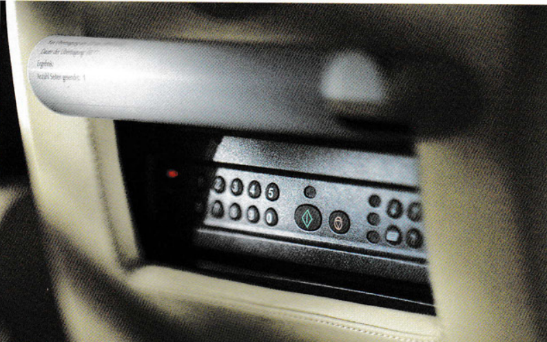
Not to be left out, BMW would also offer fax machines on certain premium 7 Series and L7 limousine models, though availability was very market-dependent. Some would stash a fax machine in the glove box, others would integrate it into the back rest of one of the front seats. Toyota was also keen to offer such facilities in its high-end models for the Japanese market. In the mid-90s, you could purchase a Toyota Celsior or Century with a fax machine secreted in the glove box. It even came with Toyota branding!
Ultimately, the in-car fax would be a relatively short-lived option in the luxury vehicle space, for several reasons. For one thing, it only became practical to offer an in-car fax in the mid-80s, when cellular networks started rolling out across major cities around the world.
By the mid-2000s, digital cell networks were taking over, and by the end of that decade, mobile internet access was trivial. It would thus become far more practical to use e-mail rather than a paper-based fax machine jammed into a car. Beyond the march of technology, the in-car fax was never going to be a particularly common selection on the options list. Only a handful of people ever really had a real need to fax documents on the go. Compared to the car phone, which was widely useful to almost anyone, it had a much smaller install base. Fax options were never widely taken up by the market, and had all but disappeared by 2010.
youtube.com/embed/0vbvu7EiWNA?…
The Toyota Celsior offered a nice healthy-sized fax machine in the 1990s, but it did take up the entire glove box.
These days, you could easily recreate a car-based fax-type experience. All you’d need would be a small printer and scanner, ideally combined into a single device, and a single-board computer with a cellular data connection. This would allow you to send and receive paper documents to just about anyone with an Internet connection. However, we’ve never seen such a build in the wild, because the world simply doesn’t run on paper anymore. The in-car fax was thus a technological curio, destined only to survive for maybe a decade or so in which it had any real utility whatsoever. Such is life!
An RP2040 Powered ADS-B Receiver

If you’ve ever heard the sound of an aircraft passing overhead and looked at an online plane tracker to try and figure out what it was, then you’ve interacted with ADS-B. It’s a protocol designed to enable easier aircraft monitoring, and it just so happens you can decode it yourself with the right hardware and software — which is how [John McNelly] came to develop ADSBee, an open source ADS-B receiver based around an RP2040.
ADS-B uses on–off keying (OOK) at 1 Mbps, and operates at 1090 MHz. This might seem like a rather difficult protocol to decode on a microcontroller, but the RP2040’s PIO is up to the task. All it takes is a bit of optimization, and a some basic RF components to amplify and digitize the signals.
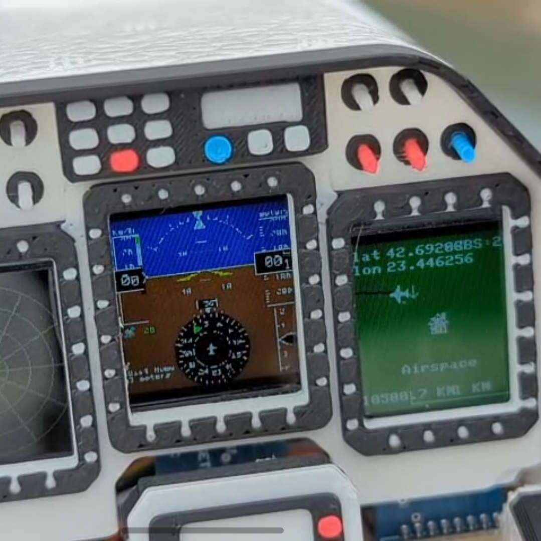
What’s quite impressive is the various form factors the module is available in. Ranging from small solder-down modules to weatherproof outdoor base stations, nearly every potential need for an ADS-B receiver is covered. With POE or ESP32 S3 options available, there is no shortage of networking options either!
ADSBees have been placed in numerous locations, ranging from base stations to drones. One user even built out a tiny flight display cluster complete with traffic indicators into an FPV drone.
This isn’t the first time we have seen ADS-B receivers used by drone enthusiasts, but this is certainly the most feature rich and complete receiver we have come across.